ESP01 and Relay
I recently dug out an old ESP-01 relay module that had been sitting in a box from past project kits at my parent’s home. Since I had couple of ESP-01 modules (ESP8266) - the one with 512k! memory; I decided to see if I could press them into service for a simple home automation task. It turned out to be a bit more of an adventure than expected!
I had standard ESP-01 and one of those common single-channel relay modules, but marked for ESP-01s. I thought it would work the same without having any issue. But as I soon discovered, it was not the case.
Although the main difference between the ESP-01 and ESP-01s is the flash memory size. The ESP-01 having 512KB of flash memory, while the ESP-01s has 1MB of flash memory. There was another difference based on which the relay module was configured.
The difference between ESP-01 and ESP-01S is the presence of built-in pull-up resistors on RST, GPIO0, and CH_PD pins in the ESP-01S. This allows the ESP-01S to enter boot mode automatically at power-up without needing external resistors, unlike the ESP-01.
Upon powering the module up, the relay was completely unresponsive. I tried some tinkering and some probing with a multimeter, but things were not working.
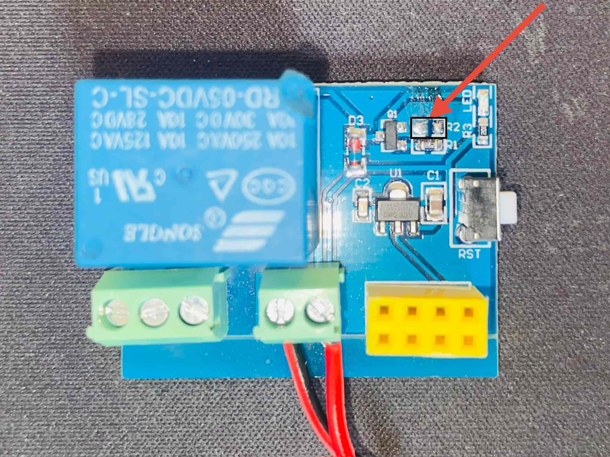
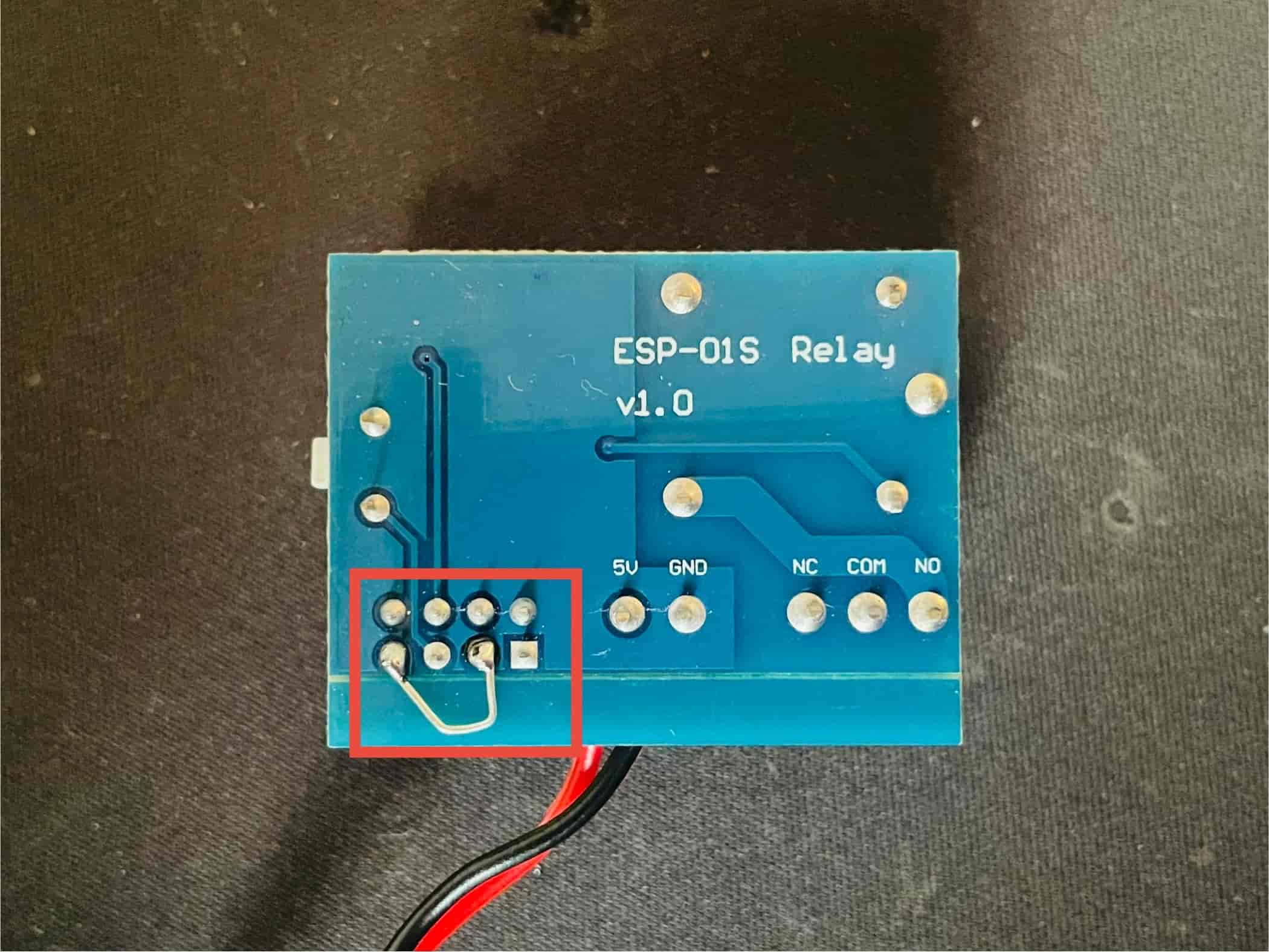
After some research, I found the difference and lucky for me, other people had tried to work on it. The fix was simple — the R2 resistor which is connect to GRIO0 needed to removed and CH_EN pin to be pulled up.
I found this Playduino’s video which helped me to fix the relay.
Since, ESP-01 has 2 GPIO pins which are directly usuable, and one is used by relay module, I decided to use the other one as a binary sensor.
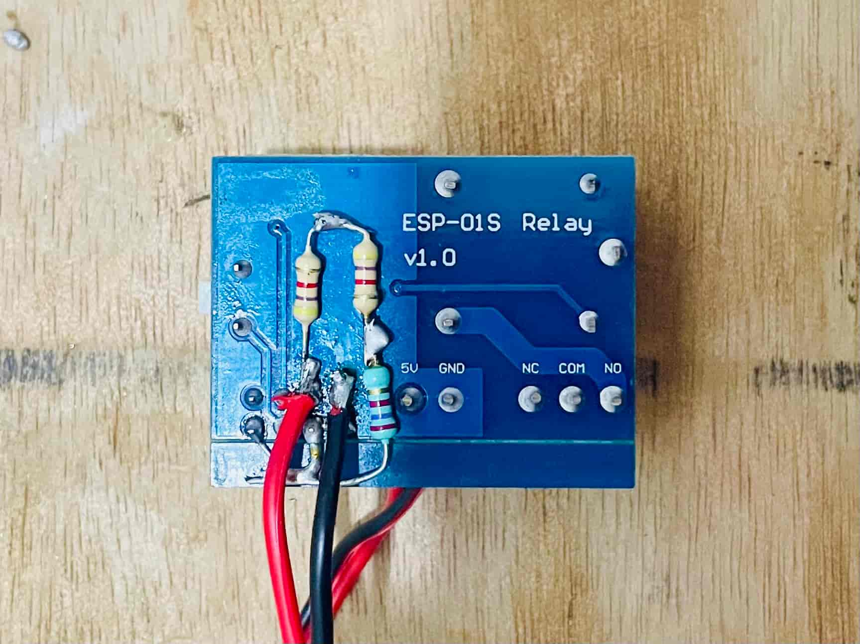
However, GPIO2 has a special role during the ESP8266’s boot process. If it’s pulled LOW at boot, the ESP-01 can enter a different boot mode. To ensure it booted correctly into normal operation mode, I added a 10kΩ pull-up resistor between GPIO2 and VCC (3.3V). This keeps GPIO2 HIGH during boot unless actively pulled LOW by a sensor or switch.
Bringing it to Life with ESPHome and Home Assistant
With the hardware mods sorted, it was time for the software. I’m a big fan of ESPHome for its simplicity and excellent integration with Home Assistant.
I am using this module in our temple lights, with the binary sensor to detect if the light switch is ON or OFF, and the relay to control the lights.
Here’s a basic ESPHome configuration for this setup:
esphome:
  name: temple-light-control
  friendly_name: Temple Light Control

esp8266:
  board: esp01

# Enable logging
logger:

# Enable Home Assistant API
api:
  encryption:
    key: <redacted>

wifi:
  ssid: !secret wifi_ssid
  password: !secret wifi_password
  fast_connect: true

switch:
  - platform: gpio
    pin: GPIO0
    name: "Temple switch"

binary_sensor:
  - platform: gpio
    pin:
      number: GPIO2
      inverted: True
      mode:
        pullup: True
        input: True
    name: "Temple board button"
I’ve set up an automation schedule for the lights to turn ON at sunset and OFF around dinner time. In addition, a binary sensor (i.e., the physical switch) is configured to trigger an automation — so toggling the switch manually will also turn the lights ON or OFF accordingly. This adds a layer of convenience for others using the setup, and most importantly, earns me the all-important wife approval factor.